THE PROCESSING PART OF THE CALCULATOR
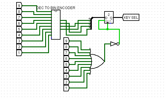
The processing part involve majorly the Operators which perform the multiplication, Division, Addition and Subtraction. Each Operator key on the Keypad is linked to each operation circuit that perform each Arithmetic operation. Each operator is connected to a multiplexer with a 2 bit selector which select 4 different operators when pressed. Below the multiplexer is a 4 to 2 encoder that connect the four operator to 2 output which goes into a register to store the data and transmit it to select part of the MUX (multiplexer). As a key operator is pressed, it select an operation and direct the result to a 4 BIT BCD. A splitter is used to split 16 bits output to different 4 bits result to be display on the 4 digits hex seven seg. Display. Create your processing part by following the diagram and choose the appropriate components from the library. Notice each tunnels on the part of the circuits, they are the connecting part of the processing parts to the Display part. Check the Display part for the same tunnels bearing the name with each tunnel in diagram. Your Display circuit should bear the same component as shown in the Diagram below.
PLEASE CLICK THIS XML FILE AND CLICK THE LINK BELOW TO COPY A FILE INTO A MS NOTE PAD AND SAVE IT AS CALCULATOR LIB.circ
This file is needed to create some of the component use in this project that is not in Logisim.
Please post comment to show areas that is not clear to you. thanks


